REPXPERT Alistair Mason is replacing the clutch & dual mass flywheel (DMF) on a 2011 Nissan Juke 1.5 dCi, with a very heavy clutch pedal. After some initial diagnosis, gearbox removal was advised & authorization given. With a recommended repair time of 4.9 hours, and all repair instructions & service information available through Schaeffler’s REPXPERT information portal, this makes a great repair for any independent workshop.
Workshop equipment required - Vehicle lift – (two post is ideal)
- Engine support
- Transmission jack
- Clutch alignment tool
Gearbox removal With the vehicle on the lift, open the bonnet and remove the following items: engine cover, battery and battery carrier (
Fig 1), air filter assembly and air filter ducting. This gives better access to the top of the gearbox. Remove the gear position switch multiplug and gear change cables (
Fig 2), there is now better access to remove the upper bellhousing bolts. Remove the hydraulic clutch pipe from the concentric slave cylinder (CSC) connection and if possible, blank the pipe to stop the fluid running out.
Raise the vehicle lift to gain access to the underside and remove the engine undertray. Remove the gearbox oil drain plug and allow the oil to drain. Lower the vehicle to waist height, remove both front wheels and both front hub nuts (
Fig 3), remove the N/S wheel arch liner, this gives access to remove the gearbox earth lead (
Fig 4) and unclip the wiring loom.
Remove or lower the front subframe to give clearance to remove the gearbox, disconnect the anti-roll bar links, bottom ball joints, remove the driveshafts, remove the steering rack to subframe bolts and support the steering rack. Remove the engine to subframe pendulum mount, and the starter motor bolts. Support the engine, remove the four subframe bolts and lower the front subframe.
With the aid of a ladder, remove the gearbox mounting, accessed from the engine bay. Support the gearbox with a transmission jack, remove the lower bell housing bolts, lower the engine and gearbox slightly, and ease the gearbox off the clutch and away from the engine. When clear, lower the gearbox and remove from the vehicle.
Clutch removal and replacement Remove the nine clutch bolts from the pressure plate and remove the clutch assembly. The clutch was examined and it could be seen that the clutch was near the end of its service life, as the clutch lining had worn close to flush with the lining rivets (
Fig 5). Due to this wear, the clutch diaphragm fingers would not be operating in their optimum position and therefore giving a heavier feeling clutch pedal.
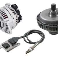
The customer had authorized replacing the dual mass flywheel as advised as best practice, so a LuK RepSet DMF was the chosen repair solution as it contains all parts required for the repair.
Remove the six DMF retaining bolts and remove the DMF, inspect the rear of the engine for any leaks. Rectify as required, then clean the back of the engine with clutch and brake dust cleaner, to avoid any contamination of the new clutch and DMF assembly.
Mount the new DMF onto the crankshaft and insert the new bolts, tighten in an even and sequential manner and torque to the manufacture’s specification. When correctly torqued, degrease the DMF face with clutch and brake dust cleaner (
Fig 6).
Remove the two CSC retaining bolts and remove the CSC. Check for any leaks, or for any play in the gearbox input shaft. Clean the bellhousing with clutch and brake dust cleaner. Carefully mount the new CSC ,taking note of the service information with reference to the clutch pipe grommet. Insert the two CSC retaining bolts and torque as required (
Fig 7).
Apply a light smear of high melting point grease to the splines on the gearbox input shaft and then mount the new clutch plate onto the input shaft. This will confirm the clutch plate is correct and also evenly distribute the grease. Remove the clutch plate and wipe off any excess grease.
Fit the new clutch onto the DMF. Mount the new clutch plate onto the DMF, ensuring “Gearbox side” is visible (
Fig 8) and then align using a clutch alignment tool. Degrease the clutch pressure plate surface with clutch and brake dust cleaner, position the clutch pressure plate onto the DMF alignment dowels, fit and tighten the nine clutch bolts in an even and sequential manner. Be sure to torque to the manufacture’s specification. Remove the clutch alignment tool.
Before fitting the gearbox, ensure the engine to gearbox alignment dowels are positioned correctly, and that all cables etc. are clear of the bellhousing area to aid gearbox fitment. At this point it is always best practice to flush the old clutch fluid out of the hydraulic system, and refill with new fluid, ensuring it is the correct specification. This will eliminate any contamination to the new seal in the CSC.
Gearbox installation Place the gearbox onto the transmission jack, raise the transmission jack and when the gearbox is close to the engine, spend a little time aligning the gearbox. Ease into position, and then onto the alignment dowels, and insert and tighten a couple of easily accessible bellhousing bolts. Using the transmission jack, raise the gearbox and install the gearbox mounting, and the engine support. The transmission jack can now be removed , and all other parts can be fitted, in reverse order of removal.
When bleeding the clutch, the bleed system has a two position CSC connection (
Fig 9), position one opens the bleed nipple. When the connection is pushed against the gearbox casing, the bleed nipple is closed. In this instance, the connection was eased back to position one, and the hydraulic system was vacuum bleed. Remember to refill gearbox oil with the correct grade and amount of oil, and reset all effected electrical consumers. Always carry out a full road test to ensure a quality repair.
Information on Schaeffler products, fitting instructions, labour times and much more can be found on the REPXPERT workshop portal - www.repxpert.co.uk - the REPXPERT app, or by calling the Schaeffler REPXPERT hotline on (+44) 1432 265 265.
To read more of this technical article or download the entire article click
here. There are lots more Tech Tips to view, and they are all searchable, on
TechTips.ie.
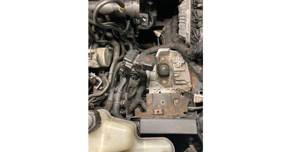 Fig. 1
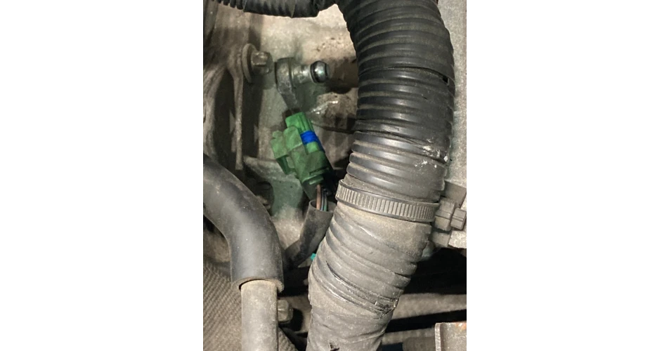 Fig. 2
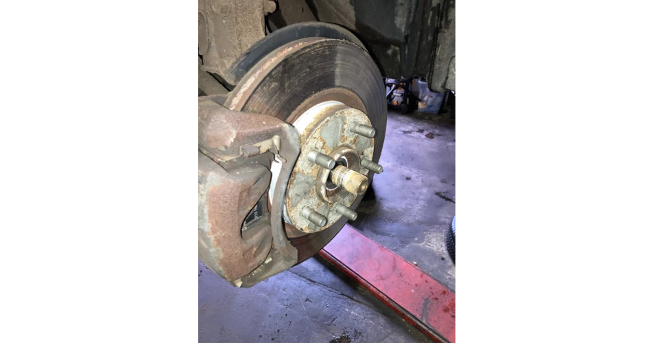 Fig. 3
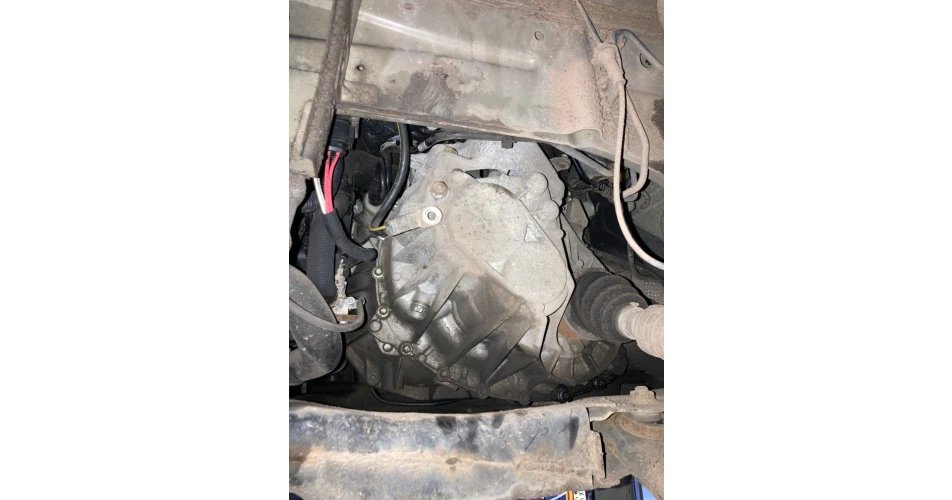 Fig. 4
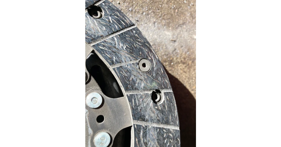 Fig. 5
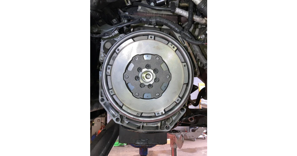 Fig. 6
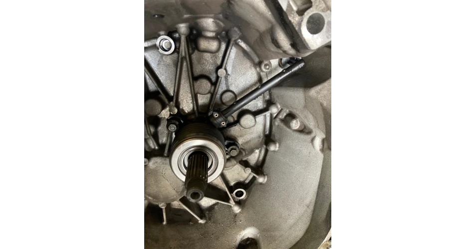 Fig. 7
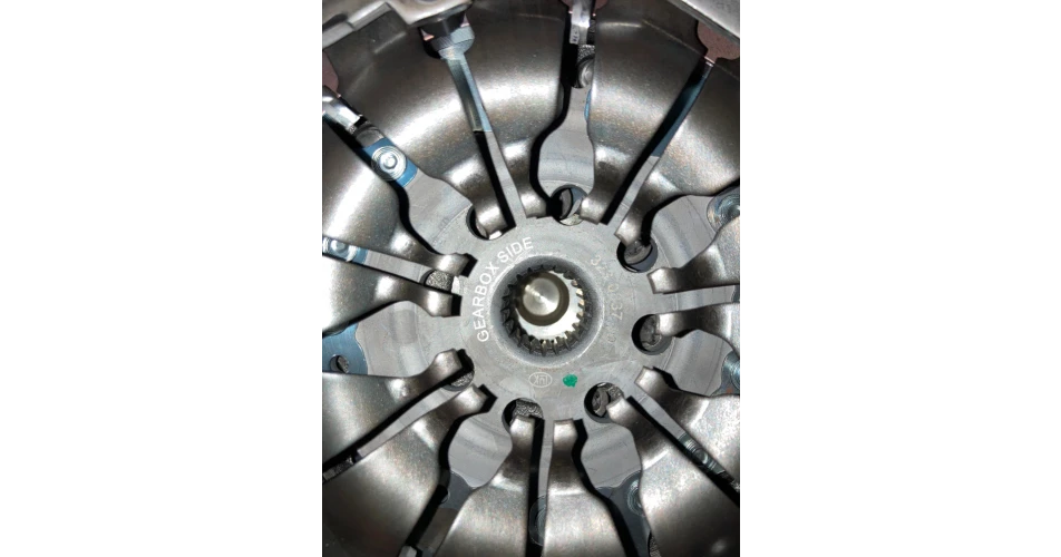 Fig. 8
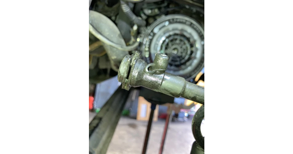 Fig. 9