A technician called the Technical Helpline about the signals he was trying to interrogate from an ABS wheel speed sensor. He had set up his scope and was getting what looked like a 12-volt signal, along with what he described as noise on the signal voltage.
We explained that the signal for this type of ABS sensor is a very small variation on the 12 Volt Bias voltage, and that the setup he was using was not the best option. Looking at the potential difference would reveal a better signal definition. This involves setting the scope voltage base to a lower level, around 100mv per division, enabling us to measure a signal of up to 1 volt. You then ground the channel to a battery positive connection point, and the signal line to the circuit in question.
In this configuration, the scope only displays the potential difference in the signal as compared to the positive battery voltage. This gives a much better definition of the wheel speed sensor signal, as the signal is normally a 300mv waveform influenced by an opposing magnetic impulse ring. The voltage range of the scope is only 1 volt, but the signal shape was clear to see.
Versatile potential difference testing Another very valuable use of potential difference, or voltage drop measurements, is in the tracking of current draw over longer time periods with the use of a scope.
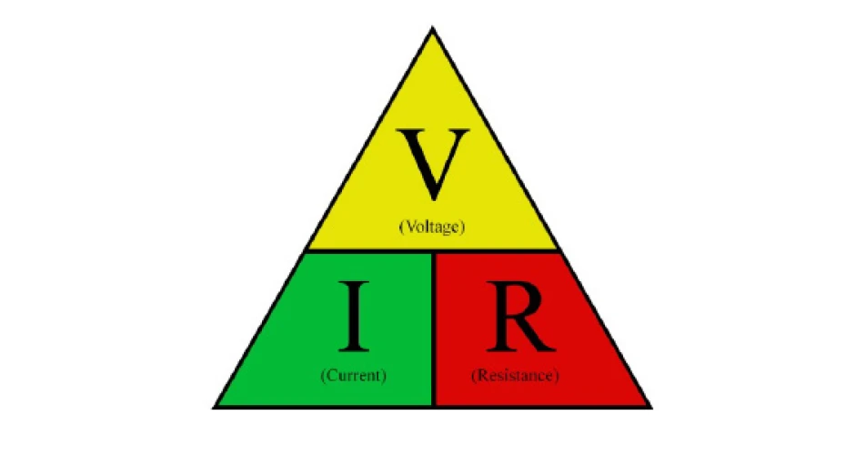
Combine this with a calculation using Ohm’s Law, you can determine the actual current through a known resistance value. Measuring a potential difference across a known resistance will give you the current flowing through the circuit. For example, a 300mv drop in potential across a 1 Ohm resistor is a 300ma current draw.
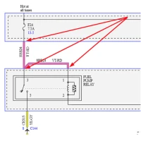
This is the basic principle of non-invasive current testing, and is very useful when tracing a parasitic drain. This is the basic principle behind the fuse charts available from Power Probe.
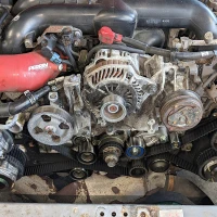
Other potential difference tests Many charging and starting system faults can be solved with the basic potential difference testing under operating loads. Any circuit should have little or no volt drop from end to end while under load. These include charging power and ground circuits.
Increased voltage drop levels seriously reduce the efficiency of a starter motor. Before condemning a slow starter, always carry out a volt drop test of both the ground circuit and live circuit. Always remember the circuit must be operating for the voltage drop to be accurate.
As a rule, a maximum potential difference (voltage drop) of 0.25volts in a high current circuit, and 0.1 volt in a low current circuit is normal. Starting and charging systems are high current components. All other systems should be considered to be low current circuits.
To see or download this article
click here. There are lots more Tech Tips to view, and they are all searchable, on
TechTips.ie.
To join the Autobiz Helpline, call 01-905-9500, and then press 2, for further information.