REPXPERT Alistair Mason is investigating a clutch fault on a 2014 Hyundai i30, which has covered more than 162,000 miles. The customer had reported that it was difficult to get the vehicle into gear. With full workshop instructions available on Schaeffler’s REPXPERT online information system, and little investment in workshop tooling required, this makes a great repair for any independent workshop. Scheduled time for this clutch replacement is 3.4 hours.
On initial diagnosis, it was noticed that there seemed to be restricted clutch pedal travel and a lot of free play in the pedal, due to excess wear at the clutch master cylinder to pedal connection (Fig 1).
The clutch master cylinder was replaced, the clutch bled and full clutch pedal travel restored, but gear selection with the engine running was still difficult. However, with the engine switched off, the gears could be selected easily, which indicated that the clutch was not fully disengaging. Authorisation was given to remove the gearbox for further investigation.
Workshop equipment required
- Vehicle lift (two-post is ideal)
- Engine support
- Transmission jack
- Clutch alignment tool
Gearbox removal Starting in the engine bay, remove the engine cover, air filter housing and intake pipe, disconnect and remove the battery and battery tray, and then the engine ECU. This gives good access to the top of the gearbox (Fig 2). Remove the engine speed sensor from the back of the bellhousing, disconnect the reverse light switch, gearbox earth strap, then disconnect both gear change cables and cable bracket, and stow them out of the way. Remove the upper bellhousing and starter motor bolts, then fit the engine support, if a bridge system is being used.
Before raising the vehicle from the ground, slacken both front hub nuts (note – on reinstallation, new hub nuts may be required if the locking tabs break), then raise the vehicle lift to waist height and remove both front wheels. Raise the lift to gain access to the underside, remove the engine undertray and the N/S splash guard (Fig 3) and drain the gearbox oil. While the oil is draining, disconnect both front bottom ball joints, ease the outer CV joints out of the hub assemblies and remove the driveshafts from the gearbox. The driveshafts may need to be levered out.
Remove the two hydraulic clutch slave cylinder retaining bolts (Fig 4) and the flex pipe bracket bolt. Ease the slave cylinder away from the gearbox, and remove the air charge cooler pipe that runs under the engine/gearbox. Detach the lower gearbox pendulum mounting and retaining bracket, as well as the tin cover plate at the bottom of the bellhousing. Remove the lower bellhousing bolts, leaving a couple of easily accessible bolts to support the gearbox until the point of removal, lower the lift to waist height and remove the two gearbox mounting bolts that are accessed through the inner wing (Fig 5), then lower the lift and remove the mounting from the gearbox. Raise the lift to gain access to the underside, support the gearbox with a transmission jack and remove the final bellhousing bolts. Ease the gearbox away from the engine. When the gearbox input shaft is clear of the clutch, lower the gearbox, remove the gearbox from the vehicle and place it somewhere safe.
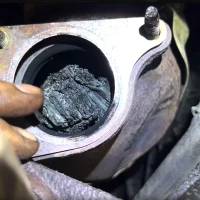
Fault diagnosis and clutch replacement Remove the clutch assembly from the flywheel by unscrewing the nine clutch retaining bolts, and ease the clutch off of the flywheel. At this point, the fault in this repair was identified (Fig 6): One of the clutch plate torsion damper springs had broken, come out of its retainer and was affecting clutch operation and clearance.
This spring can break from excess load/hard driving or vibration, from an engine misfire for example, being transmitted through the clutch, causing the springs to fully compress and then break.
With the clutch removed, clean the back of the engine and flywheel with clutch and brake dust cleaner, inspect for any leaks, and rectify if required. Also, remove the glaze from the flywheel clutch plate surface using an Emory cloth.
Remove the release bearing from the gearbox and clean the bellhousing area with clutch and brake dust cleaner, and check the bearing guide tube for wear (Fig 7) as it is known for both Hyundai and Kia engines to wear in this area and cause release problems.
Apply a light smear of high melting point grease onto the gearbox input shaft spline and mount the new clutch plate onto the input shaft, this will ensure the clutch plate is the correct fitment and also evenly distribute the grease. Remove the clutch plate and wipe off any excess grease.
Clean the new clutch pressure plate with clutch and brake dust cleaner, to ensure the face is degreased and, using a clutch alignment tool, mount the new clutch (Fig 8). Tighten the bolts in an even and sequential manner and then torque to the manufacturer’s specification, before removing the clutch alignment tool.
Check that all cables, wires and hoses are clear of the bellhousing area, so as not to interfere with the gearbox installation, and make sure that the engine to gearbox alignment dowels are installed correctly.
Gearbox installation Using a transmission jack, ease the gearbox into position, taking time to ensure the heights and angles are correct. Ensure that the gearbox mounts on the alignment dowels and, once home, insert and tighten a couple of easily accessible bellhousing bolts. Refit all other components in reverse order of their removal, and torque all bolts to the manufacturer’s specification.
After the battery lead has been connected, reset all required electrical systems and carry out a full road test to ensure that the repair has been successfully completed.
Information on Schaeffler products, fitting instructions, labour times and much more can be found on the REPXPERT workshop portal - www.repxpert.co.uk - the REPXPERT app, or by calling the Schaeffler REPXPERT hotline on (+44) 1432 265 265.
To read more of this technical article or download the entire article click
here. There are lots more Tech Tips to view, and they are all searchable, on
TechTips.ie.
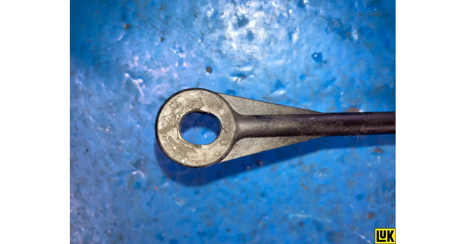 Fig. 1
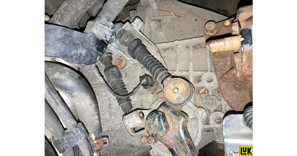 Fig. 2
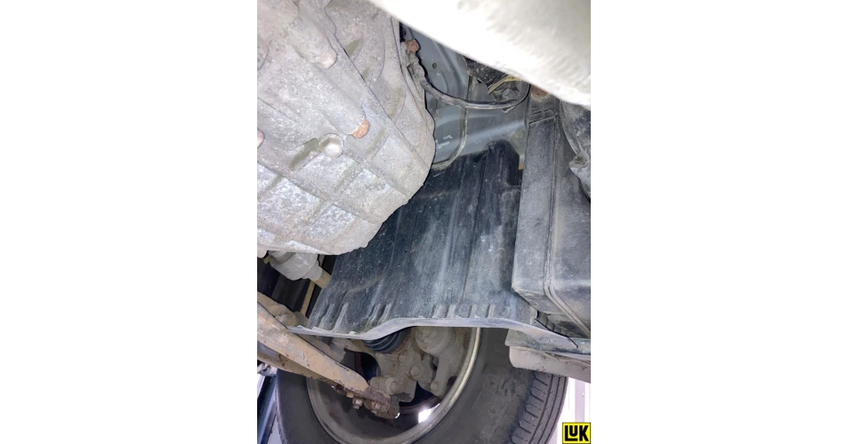 Fig. 3
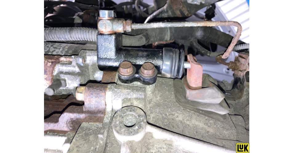 Fig. 4
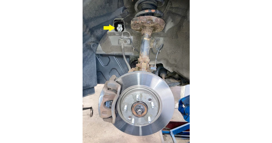 Fig. 5
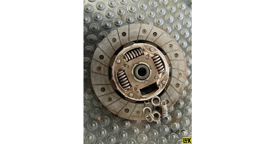 Fig. 6
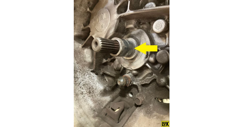 Fig. 7
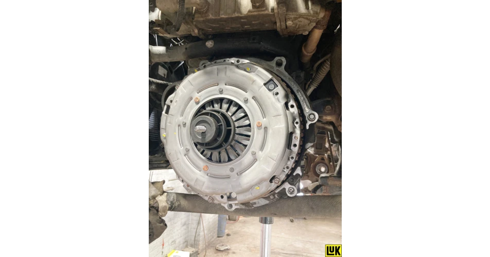 Fig. 8