REPXPERT Bob Carter is replacing a clutch and dual mass flywheel (DMF) in a 2013 Opel Mokka, fitted with a 1.7 CDTI engine. With a little insight into this repair, an independent workshop will be able to confidently replace the clutch system on this engine in this vehicle. The scheduled time for this repair is 6.5 hours.
The following workshop equipment is required:
- Vehicle lift (two post is preferred)
- Engine support
- Transmission jack
- Oil drainer
- Gearbox oil dispenser
- SAC Tool kit
- DMF Testing tool
- Clutch vacuum bleed tool
With the vehicle positioned on the ramp with the front wheels removed, remove the steering column to steering rack pinch bolt located in the driver’s foot well, and disconnect the steering column from the rack. Open the bonnet, disconnect the battery terminals and remove the battery, as well as the ECU clipped to the side of the battery carrier, then unclip the wiring loom from the battery carrier. This now gives good access to the top of the gearbox. Clamp the flexible part of the hydraulic clutch pipe and disconnect the pipe from the concentric slave cylinder (CSC) by releasing the clip. Remove the gear cables from the linkage by levering them off, and stow in the bulkhead area.
Install an engine bridge to support the weight of the engine and then hold the coolant radiator in position, by attaching two cable ties through the radiator and fixing them to the engine bridge, which prevents the radiator moving when the front subframe is lowered. There is also an ABS wiring loom attached to the ABS unit that needs to be unclipped to allow some additional free play on the loom, when the subframe is lowered.
Remove the retaining nuts that hold the engine wiring loom bracket to the top of the bell housing, detach the small bracket by the CSC and then take out the top bell housing bolts.
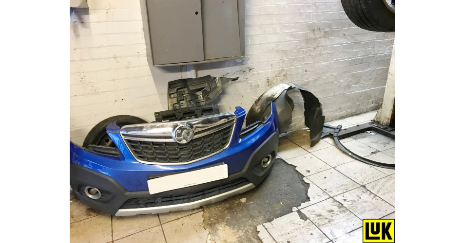
Remove the front bumper cover to gain access to the front subframe bolts, but take care when disconnecting the wheel arch trim clips as these can easily be broken (Fig. 1). Remove the wheel arch liners and underbody tray.
Disconnect the exhaust rubber from the subframe and the exhaust at the downpipe flange, then unbolt the steering rack and anti-roll bar from the subframe. Remove the cross-support bar from the subframe and the gearbox side subframe bolts and loosen the opposite side, which will allow the gearbox side of the subframe to drop low enough to clear the gearbox.
Drain the gearbox oil. Disconnect the bottom ball joint and pull out the drive shaft from the gearbox and stow with cable ties out of the way.
With the engine supported, remove the rear gearbox mounting and the bolts for the front mounting, which stays attached to the subframe. Refit and torque in the oil drain plug.
Remove the top gearbox mounting and lower the engine and gearbox slightly to allow the gearbox to clear the body and subframe.
Support the gearbox using a transmission jack and remove the final bell housing bolts, noting their designation, and ease the gearbox away from the engine. Once clear, with the help of a second person to lift the gearbox over the side of the lowered subframe, the gearbox can be removed and placed away from the vehicle.The three small yellow springs on the self-adjusting clutch mechanism had extended, indicating it was near the end of its adjustment.
Remove the clutch assembly from the flywheel by removing the six bolts and ease the clutch assembly off the DMF.
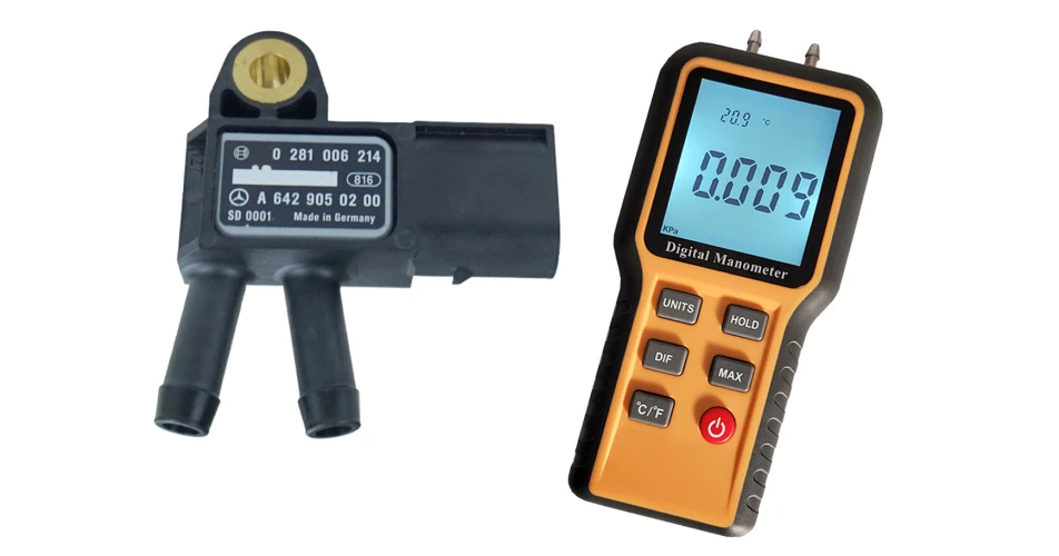
Whenever undertaking clutch replacement, it is best practice to establish the extent of the wear to the DMF by measuring it against its specification (Fig. 2). However, they all have different measurements, depending on the part number, although helpfully, these specifications can readily be found using the REPXPERT app. In addition to excessive wear, any scoring, heat damage or excessive grease loss would also require DMF replacement.
Remove the six flywheel bolts and then the DMF, which provides the opportunity to check for any leaks from the engine (oil or coolant) that could contaminate the new flywheel and clutch assembly and to rectify them, if required.
Remove any clutch dust from the engine using brake and clutch dust cleaner, before mounting the new flywheel, as this could contaminate the new components. Check the new flywheel is correct by comparing its dimensions and the ring gear teeth. Mount the new DMF ensuring any alignment dowels are correctly positioned and secure it into place using new flywheel bolts, which must be tightened in an even and sequential process and torqued to the manufacturer’s specification. Flywheel bolt torques can also easily be obtained from Schaeffler’s DMF Checkpoint app.
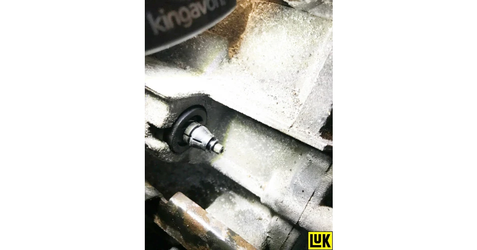
Remove the CSC from the bell housing on the gearbox, but first remove the black plastic 3-way adaptor from the gearbox by releasing the small spring retaining clip, and then ease it away from the gearbox (Fig. 3 ).
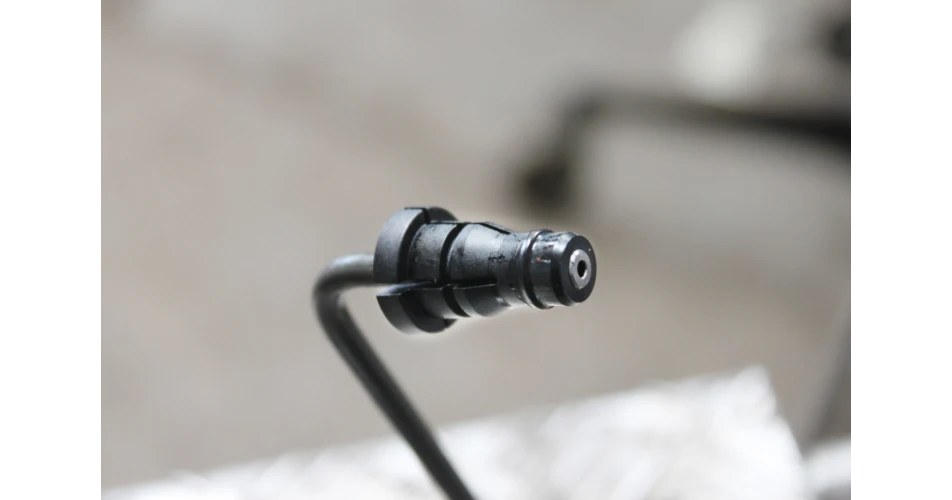
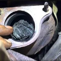
At this point look for a black rubber seal (Fig. 4) that should stay with the pipe. If it is not there, look for it within the 3-way adaptor, because if it is not removed it will act like a one-way valve and is likely to cause the new CSC to burst on bleeding the clutch.
Remove the black plastic bush that positions the CSC pipe as it passes through the bell housing, as well as the three retaining bolts from the CSC, and remove it from the input shaft and gearbox.
Check that there are no oil leaks from the input shaft oil seal, rectifying if necessary, and clean the bell housing using brake and clutch dust cleaner. Then ensuring it is mounted squarely, fit the new CSC and tighten the bolts correctly, without the use of power tools. Bolt down progressively and torque down carefully, because if the mounting is misaligned, the back plate will not be secure and will leak.
Refit the black plastic location bush onto the pipe and position correctly in the bell housing. Apply a light smear for brake fluid on new seal, and ease the connector into position until the spring clip locates correctly. Lightly smear some high melting point grease on the gearbox input shaft, then locate the new clutch plate onto the input shaft, moving it back and forth a couple of times, which will both evenly distribute the grease on the input shaft and ensure the clutch plate splines are of the correct fitment. Remove the clutch plate and wipe off any excess grease.
Now fit the new clutch to the DMF, but first ensure the clutch plate is fitted the correct way with “Gearbox Side” or “Getriebe Seite” stamped on the centre of the clutch plate facing the gearbox.
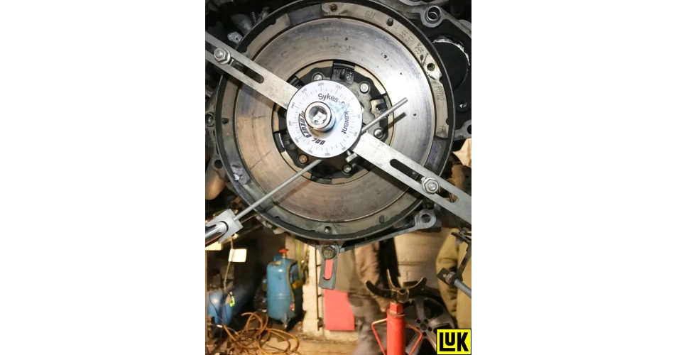
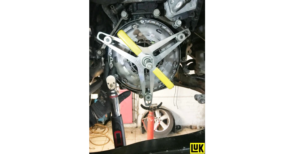
Use the Special Tool (SAC tool) to install the clutch (Fig. 5 ), as this does three things: gives perfect alignment, prevents the risk of de-adjustment and operates the clutch before the gearbox is reinstalled. This avoids the risk of a rejected warranty claim and the need to do the job again.
One final process before installing the gearbox is to flush out the old clutch fluid from the system, by draining it into a waste container and replenishing it with new clean clutch fluid, by pouring it into the reservoir. When the new fluid is flowing through the system, clamp the hose and the gearbox is now ready for installation. Finally, check that the gearbox alignment dowels are installed correctly in the engine block and that the spacer plate is aligned correctly.
Lift the gearbox into position over the subframe, support the gearbox with the transmission jack, but ensure the gearbox is positioned correctly on the jack so it will align correctly with the engine as it is eased into position, and when in position, secure it using an accessible bell housing bolt.
Re-assembly is in reverse order of removal, but remember to refill the gearbox with the correct quantity and specification of oil and torque all bolts to the manufacturer’s specification.
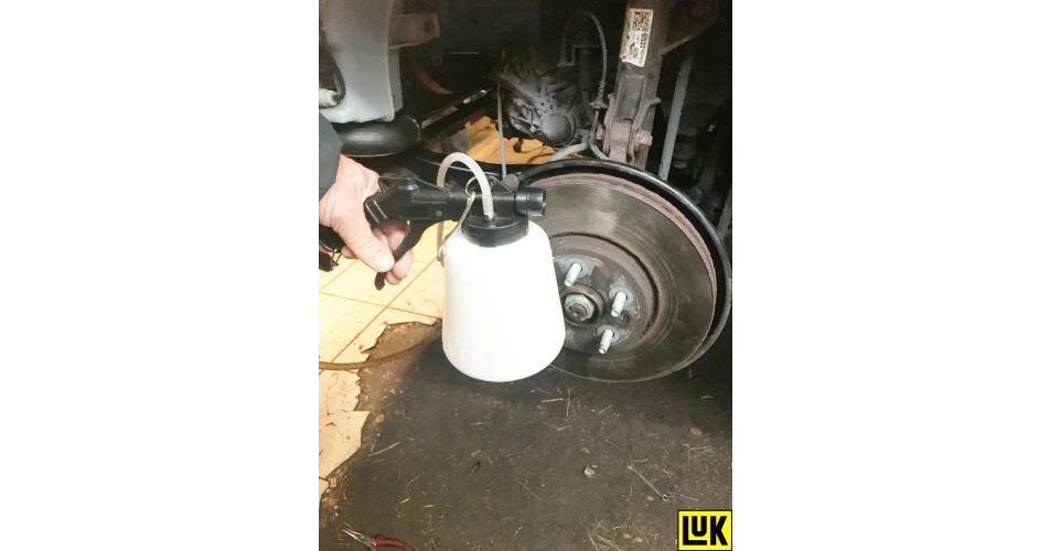
Bleeding the clutch is best done using a vacuum bleeding tool (Fig. 6 ). This is recommended by vehicle manufacturers as it eliminates the risk of over pressurisation and makes it a straightforward one-person operation.
Reset all electrical devices and carry out a full road test to ensure a complete and successful repair.
Information on Schaeffler products, fitting instructions, labour times and much more can be found on the REPXPERT garage portal – www.repxpert.co.uk – the REPXPERT app, or by calling the Schaeffler REPXPERT hotline on (+44) 1432 265265.
To read more of this technical article or download the entire article click
here. There are lots more Tech Tips to view, and they are all searchable, on
TechTips.ie.