REPXPERT Alistair Mason is replacing the clutch & dual mass flywheel in a 2013 Mini Countryman ALL4 (R60), fitted with 1.6 turbo PSA engine. As this model is four-wheel drive, it may put some independent garages off taking it on, but as this feature indicates, it’s a straightforward repair with minimum investment in special tools. With a book time of 6.7 hours, this makes a great repair for any independent garage.
Workshop equipment used,
- Vehicle lift (two-post is ideal)
- Engine support
- Transmission jack
- Clutch alignment tool
- Internal circlip pliers
Gearbox removal With the vehicle placed on the vehicle lift, slacken the front wheel locking bolts and the front hub nuts, then open the bonnet and disconnect the battery earth lead, remove the engine control unit cover, engine control unit, fuse box lid, and unbolt the fuse box and stow to one side. Remove the fuse box and control unit retaining bracket. This gives good access to the upper area of the gearbox.
Disconnect the gear change cables and unbolt the cable retaining bracket, followed by the earth point next to the gearbox mounting. Disconnect the reverse light switch and remove the upper bell housing bolts.
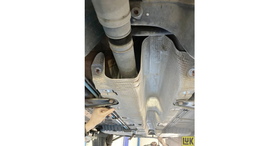
Raise the vehicle lift to gain access to the underside and remove the complete exhaust system by removing the floor braces, then the exhaust down pipe clamp and ease the rubber mountings off their mounting points. With the exhaust system removed, take off the heat shield to gain access to the prop shaft (Fig 1).
Remove the driveshafts by taking off the front wheels, releasing both bottom ball joints, disconnecting both anti-roll bar links, unbolting the headlight level sensor from the O/S bottom arm (Fig 2) and removing both hub nuts. Ease the driveshafts out of the hubs and then lever the inner joints out, and once free, remove from the vehicle.
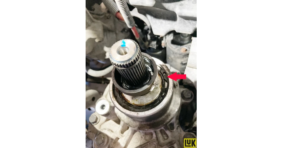
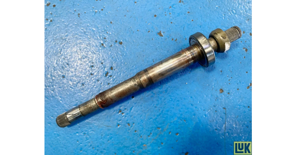
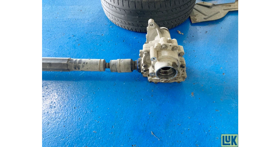
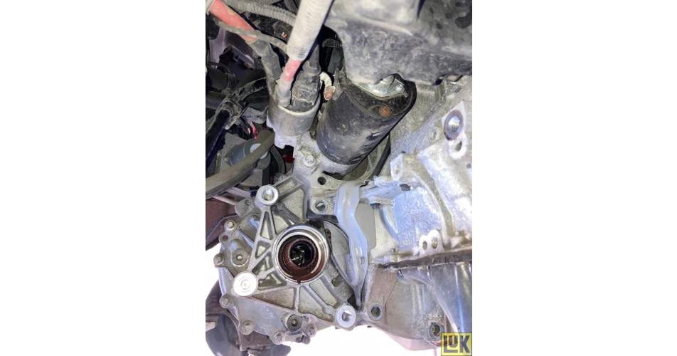
Remove the gearbox transfer box and prop shaft in the following sequence: Unbolt the driveshaft cover from the transfer box, remove the large circlip that retains the driveshaft in the transfer box (Fig 3), pull out the shaft from the transfer box (Fig 4). Remove the transfer box retaining bolts, disconnect the prop shaft from the rear differential, unbolt the prop shaft centre bearing, ease the transfer box away from the gearbox and remove the assembly from the vehicle (Fig 5).
Remove the front sub frame by detaching the lower gearbox pendulum mount, unbolt the steering rack from the subframe, remove the sub frame retaining bolts, ease the subframe backwards to release the front area and lower it from the vehicle. At the front of the gearbox, unbolt the clutch slave cylinder, leaving the hydraulic pipe connected, and stow it away from the gearbox. Disconnect the multiplug for the gear recognition switch located above the clutch slave cylinder. Remove the starter motor bolts (Fig 6) followed by the remaining bellhousing bolts, leaving one or two easily accessible bolts to support the gearbox until its removal.
Support the engine and then the gearbox using a transmission jack. Remove the gearbox mounting and then lower the engine and gearbox slightly to aid gearbox removal and remove the final bell housing bolts and ease the gearbox away from the engine. When it’s clear, lower the gearbox on the transmission jack and place it safely.
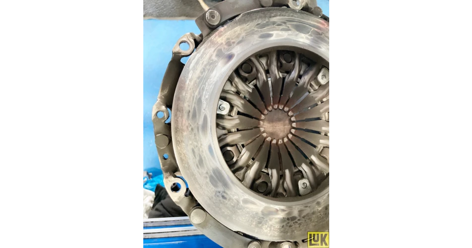
Clutch replacement With the clutch now fully accessible, remove the six clutch pressure plate retaining bolts, ease the pressure plate off the dowels and remove with the clutch plate, noting which side faces the clutch and flywheel.
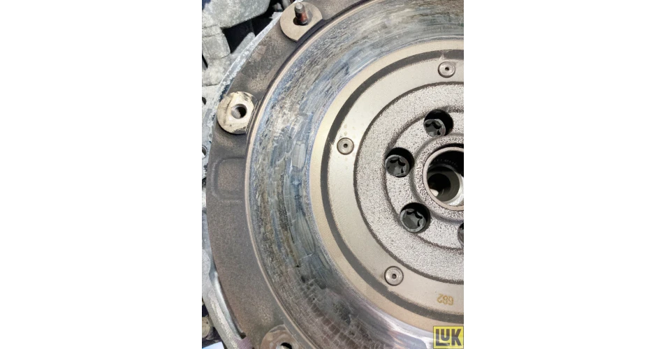
On inspection, it was evident that the clutch had been slipping. The pressure plate and dual mass flywheel faces were ‘blued’ (Fig 7 & 8), so the dual mass flywheel was replaced.
Secure the new dual mass flywheel in position with the new bolts supplied and torque to the manufacturer’s specification (torque values are easily obtained through the Schaeffler REPXPERT platform).
Follow the usual proven process of cleaning the gearbox bellhousing, checking pivot points and guide tubes for wear, applying a light smear of high melting point grease to the gearbox input shaft splines, and then mounting the clutch plate to ensure correct fitment and to evenly distribute the grease, and then taking it off to remove any excess grease. In addition, always check the release arm as these are prone to wear and cracking close to the release bearing. If the arm is in good condition, mount it with a new release bearing.
Degrease the flywheel face and the pressure plate face with clutch and brake dust cleaner. Using a clutch alignment tool, mount the clutch plate and cover, install, tighten and torque the clutch bolts in an evenly and sequentially. Always rectify any engine or gearbox leaks that could contaminate the new clutch assembly.
Gearbox installation Ensure the engine to gearbox alignment dowels are installed in the engine and that pipes and wires are clear, so as not to get caught by the gearbox on insertion. Using the transmission jack, ease the gearbox into position, and locate onto the dowels, using a couple of easily accessible bolts. Insert and tighten to secure the gearbox in position.
Installation is in reverse order of removal, but remember to torque the required bolts to the manufacturer’s specification. When the battery lead has been reconnected, reset all electrical consumers.
Finally, carry out a full road test to ensure the quality of the repair.
Information on Schaeffler products, fitting instructions, labour times and much more can be found on the REPXPERT workshop portal - www.repxpert.co.uk - the REPXPERT app, or by calling the Schaeffler REPXPERT hotline on (+44) 1432 265265.
To read more of this technical article or download the entire article click
here. There are lots more Tech Tips to view, and they are all searchable, on
TechTips.ie.

-4.jpg)
-6.jpg)